Silicon offers an unusually high lithium-storage potential, yet a useful silicon electrode is not created by capacity alone. Repeated alloying and dealloying can generate major dimensional change, disrupt electrical contact and continuously expose fresh surface to the electrolyte. Silicon-based nanocomposites address that problem at the material-architecture level by combining nanoscale silicon or silicon oxide with conductive, mechanically accommodating and interface-controlling phases.
Eata Silicon supports sourcing across nano-silicon feedstocks and engineered composite families, including silicon/carbon (Si/C), carbon-coated silicon, silicon/graphite, silicon/graphene, silicon/CNT, porous silicon/carbon and SiOx/C systems. Material selection can be built around composition, particle-size distribution, secondary-particle morphology, carbon architecture, surface chemistry, oxygen level, impurity controls and the downstream electrode process rather than around a generic "silicon anode" label.
From Nano-Silicon to an Engineered Composite Interface
The most important distinction is where the surrounding phase sits and what it is expected to do. A simple physical blend of nano-silicon and graphite is different from a secondary particle in which silicon is embedded in a carbon framework; a conformal carbon coating is different again from a porous shell that intentionally leaves internal room around the silicon. Each architecture changes the balance among conductivity, mechanical constraint, accessible surface area, tap density, slurry behavior and electrolyte exposure.
Carbon is therefore more than a conductive additive in many Si-based nanocomposites. Amorphous carbon, graphite, hard carbon, graphene and carbon nanotubes can be used as coatings, scaffolds, conductive bridges or matrix phases. The optimum route depends on how much silicon is required, how the powder must pack and process, and which failure mode is most important to control in the intended cell design.
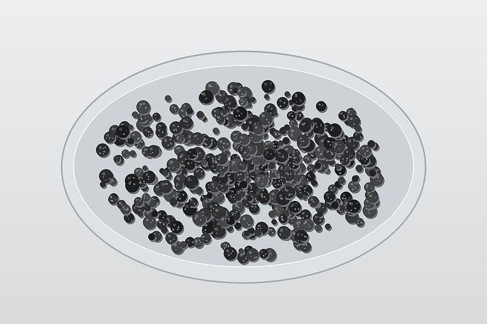 Fig. 1. Engineered silicon–carbon composite granules represented as a free-flowing secondary-particle feedstock concept.
Material Architectures Buyers Commonly Compare
1. Silicon/Carbon (Si/C) Composite Powder
Si/C is a broad family rather than a single composition. Silicon may be dispersed through amorphous carbon, confined inside a porous carbon scaffold, attached to graphite-like domains or incorporated into a larger secondary particle. The carbon phase is commonly used to maintain electronic pathways and to help the composite tolerate repeated dimensional change. When comparing Si/C powders, ask how the silicon is distributed, what type of carbon is used, whether the particle is primary or secondary, and how porosity is controlled.
2. Carbon-Coated Silicon, Core–Shell and Yolk–Shell Structures
A carbon coating can reduce direct electrolyte exposure and provide a more continuous conductive surface around silicon. Core–shell and yolk–shell concepts push the architecture further: the shell surrounds a silicon-rich core, while engineered internal void space can give the active phase room to expand without forcing the outer particle boundary to follow every dimensional change. Shell continuity, carbon chemistry, wall thickness, internal void fraction and particle integrity are therefore useful specification topics.
 Fig. 2. Cutaway concept of a silicon-rich core enclosed by a porous carbon shell with internal expansion space.
3. Silicon/Graphite Composite Anode Materials
Silicon/graphite systems are practical when a formulation needs to retain the processing familiarity and packing behavior of graphite while adding a higher-capacity silicon component. The silicon can be introduced as a discrete blend, deposited or coated on graphite, or built into composite secondary particles. Useful comparison points include graphite morphology, silicon distribution, particle-size match, carbon coating, surface area, tap density and how the blend behaves at the intended electrode loading.
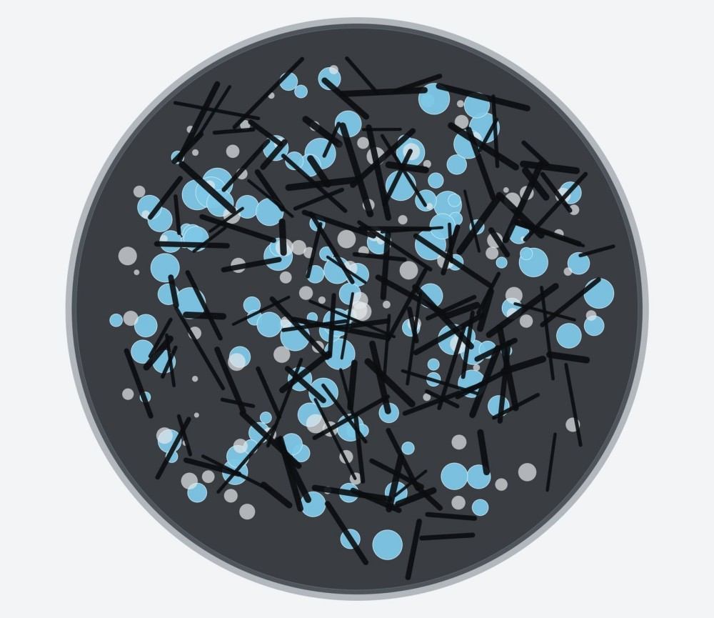 Fig. 3. Cross-sectional concept of a spherical Si/graphite/carbon secondary particle containing conductive flakes, nanosilicon domains and controlled porosity.
4. Silicon/Graphene and Silicon/CNT Nanocomposites
Graphene-type sheets and carbon nanotube networks are widely studied as conductive frameworks around silicon because they can connect separated active domains while adding mechanical flexibility at nanoscale. These architectures can be attractive when the project is focused on network conductivity, interparticle contact or lightweight conductive scaffolding. The quality of dispersion matters as much as the carbon identity: agglomerated nanosilicon or poorly distributed nanocarbon can defeat the intended network design.
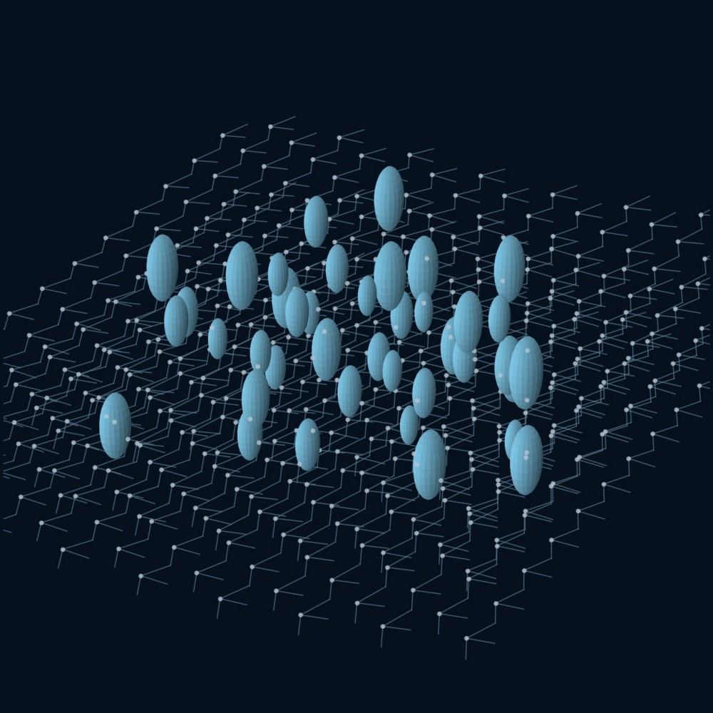 Fig. 4. Silicon nanodomains distributed through a layered graphene-like conductive network.
5. Porous Silicon/Carbon and SiOx/C Systems
Porous Si/C structures deliberately create internal free volume and transport pathways around the active phase. SiOx/C materials take a different route by using partially oxidized silicon chemistry together with a carbon phase. SiOx can reduce the magnitude of expansion compared with elemental silicon, but the trade-off can include lower active-silicon content and lower initial Coulombic efficiency. For sourcing, the "x" in SiOx, oxygen content, carbon coating, particle architecture and qualification method should be treated as part of the material identity—not as secondary details.
Representative Product Families
| Product Family |
Typical Architecture |
Form |
Keywords |
Key Selection Focus |
| Nano Silicon Powder / Silicon Nanoparticles |
Elemental Si nanopowder |
Powder |
nano silicon powder; silicon nanoparticles; silicon anode powder |
Purity, oxygen, PSD, surface area, surface condition |
| Carbon-Coated Silicon Nanoparticles |
Si with carbon surface layer |
Powder |
carbon coated silicon; C-coated Si nanoparticles; silicon carbon coating |
Coating continuity, carbon content, oxygen, primary particle size |
| Silicon/Carbon Composite |
Si dispersed or embedded in carbon |
Composite powder |
Si/C composite; silicon carbon anode material; silicon-carbon composite powder |
Si:C ratio, carbon type, secondary particle size, porosity, tap density |
| Porous Silicon/Carbon Composite |
Porous Si and carbon scaffold |
Composite powder |
porous Si/C; porous silicon carbon anode; nanoporous silicon carbon |
Pore architecture, carbon framework, particle integrity, surface area |
| Silicon/Graphite Composite |
Si combined with natural or synthetic graphite |
Composite / blend |
silicon graphite composite; Si/graphite anode material; silicon graphite powder |
Graphite type, Si distribution, PSD matching, tap density |
| Silicon/Graphene Nanocomposite |
Si integrated with graphene-like sheets |
Hybrid powder |
silicon graphene composite; Si/graphene anode; graphene silicon nanocomposite |
Si anchoring, sheet dispersion, conductive network, agglomeration control |
| Silicon/CNT Composite |
Si coupled with carbon nanotube network |
Hybrid powder |
silicon CNT composite; Si carbon nanotube anode material |
CNT type, dispersion, Si contact, composite morphology |
| Si@C Core–Shell / Yolk–Shell |
Silicon enclosed by carbon shell |
Engineered powder |
Si@C core shell; yolk shell silicon carbon; hollow silicon carbon composite |
Shell integrity, void space, carbon chemistry, particle robustness |
| SiOx/C Composite |
Silicon oxide plus carbon phase |
Composite powder |
SiOx/C anode material; silicon oxide carbon composite; SiO carbon anode |
Oxygen state, carbon coating, ICE trade-off, composition |
| SiOx/Graphite Composite |
SiOx integrated or blended with graphite |
Composite / blend |
SiOx graphite anode; silicon oxide graphite composite |
SiOx fraction, graphite compatibility, surface area, electrode processing |
| Silicon/Conductive-Polymer Nanocomposite |
Si incorporated into conductive polymer matrix |
Composite powder |
silicon polymer anode; silicon polyaniline composite; nano-Si conductive polymer |
Polymer chemistry, coating/encapsulation, Si loading, dispersion |
| Surface-Modified Silicon Nanocomposite |
Si with tailored oxide, carbon or organic interface |
Powder / dispersion |
surface modified silicon nanoparticles; functionalized silicon nanocomposite |
Surface functionality, compatibility, moisture, dispersion medium |
| Nanosilica/Polymer Nanocomposite |
Nanoscale SiO2 in polymer-rich matrix |
Powder / concentrate / dispersion |
silica polymer nanocomposite; nanosilica hybrid resin; dielectric nanocomposite |
Surface treatment, particle dispersion, solids, matrix compatibility |
| POSS/Polymer Nanocomposite |
Silsesquioxane nanodomains in polymer matrix |
Additive / resin component |
POSS polymer nanocomposite; silsesquioxane hybrid composite |
POSS functionality, matrix chemistry, loading approach, dispersion |
What to Specify Before Comparing Silicon Nanocomposite Powders
| Decision Point |
What to Define |
Why It Matters |
| Silicon chemistry |
Elemental Si, SiOx or mixed silicon-containing phase |
Changes lithium-storage mechanism, expansion behavior, oxygen content and initial efficiency. |
| Composite composition |
Silicon fraction, carbon fraction, graphite or other secondary phase |
Determines how much active silicon is present and which phase supplies conductivity or mechanical support. |
| Particle-size distribution |
Primary particle scale plus secondary-particle D10/D50/D90 where relevant |
Influences slurry behavior, surface area, packing, coating uniformity and electrode density. |
| Morphology / architecture |
Coated particle, porous composite, core–shell, yolk–shell, spherical secondary particle, flake-rich blend |
Architecture determines where expansion space, conductive paths and exposed surface are located. |
| Surface area / porosity |
BET surface area and pore information when important |
Higher surface area can aid interfacial access but also increases the area available for electrolyte reaction. |
| Tap density |
Powder packing characteristic under a defined method |
Important when volumetric electrode design and coating density matter. |
| Oxygen / surface oxide |
Bulk oxygen or defined surface-oxide condition |
Can influence interfacial chemistry, initial efficiency and the identity of SiOx-based materials. |
| Moisture and impurities |
Water plus selected metal or process-related impurity limits |
Supports reproducible slurry processing and qualification of sensitive electrochemical systems. |
| Surface treatment / carbon coating |
Carbon chemistry, coating method, functionalization or dispersion aid |
Controls wetting, compatibility, conductivity and interfacial exposure. |
| Electrochemical test protocol |
Electrode recipe, active loading, binder, conductive additive, electrolyte, voltage window, formation and rate |
Electrochemical figures are only comparable when the test conditions are understood. |
Where Silicon-Based Nanocomposites Fit in Energy Materials
High-Capacity Lithium-Ion Anodes
The strongest commercial interest in silicon nanocomposites is in negative-electrode materials that can raise capacity beyond conventional graphite-only designs. The role of the composite is to make that additional silicon usable: maintain conductive contact, manage dimensional change, limit repeated interface disruption and preserve a powder morphology that can still be processed into an electrode. Si/C and Si/graphite materials are therefore often discussed not only by capacity, but also by swelling, initial efficiency, loading, density and cycle stability under a defined cell design.
Graphite-Blended and Silicon-Rich Formulations
A project does not have to move directly from graphite to a silicon-rich anode. Silicon/graphite composites and silicon-containing blends allow material developers to adjust silicon contribution against familiar graphite processing. At the other end of the spectrum, porous carbon scaffolds, low-swell Si/C architectures and engineered secondary particles are being developed for much higher silicon utilization. The correct raw material depends on the target electrode design, not on the highest headline silicon percentage.
Fast-Charge, High-Loading and Interface-Focused Development
Particle architecture becomes especially important when the electrode is pushed toward higher loading, faster charging or long cycling. Short diffusion distances, conductive carbon pathways and controlled internal voids can be useful design tools, but they must be balanced against surface area, side reactions and electrode density. For that reason, a sourcing discussion should include mass loading, target areal capacity, compaction approach, binder system and electrolyte environment whenever those factors are already defined.
Electrical, Dielectric and Hybrid Polymer Nanocomposites
Silicon-based nanocomposites also extend beyond alloying anodes. Surface-modified nanosilica, organosilica nanoparticles and silsesquioxane-rich domains can be combined with polymer matrices for electrical insulation, dielectric, barrier, coating and polymer-electrolyte development. In these systems the key purchasing questions shift from lithium-storage capacity to particle dispersion, surface functionality, solids content, matrix compatibility, viscosity and the electrical or mechanical role of the inorganic nanophase.
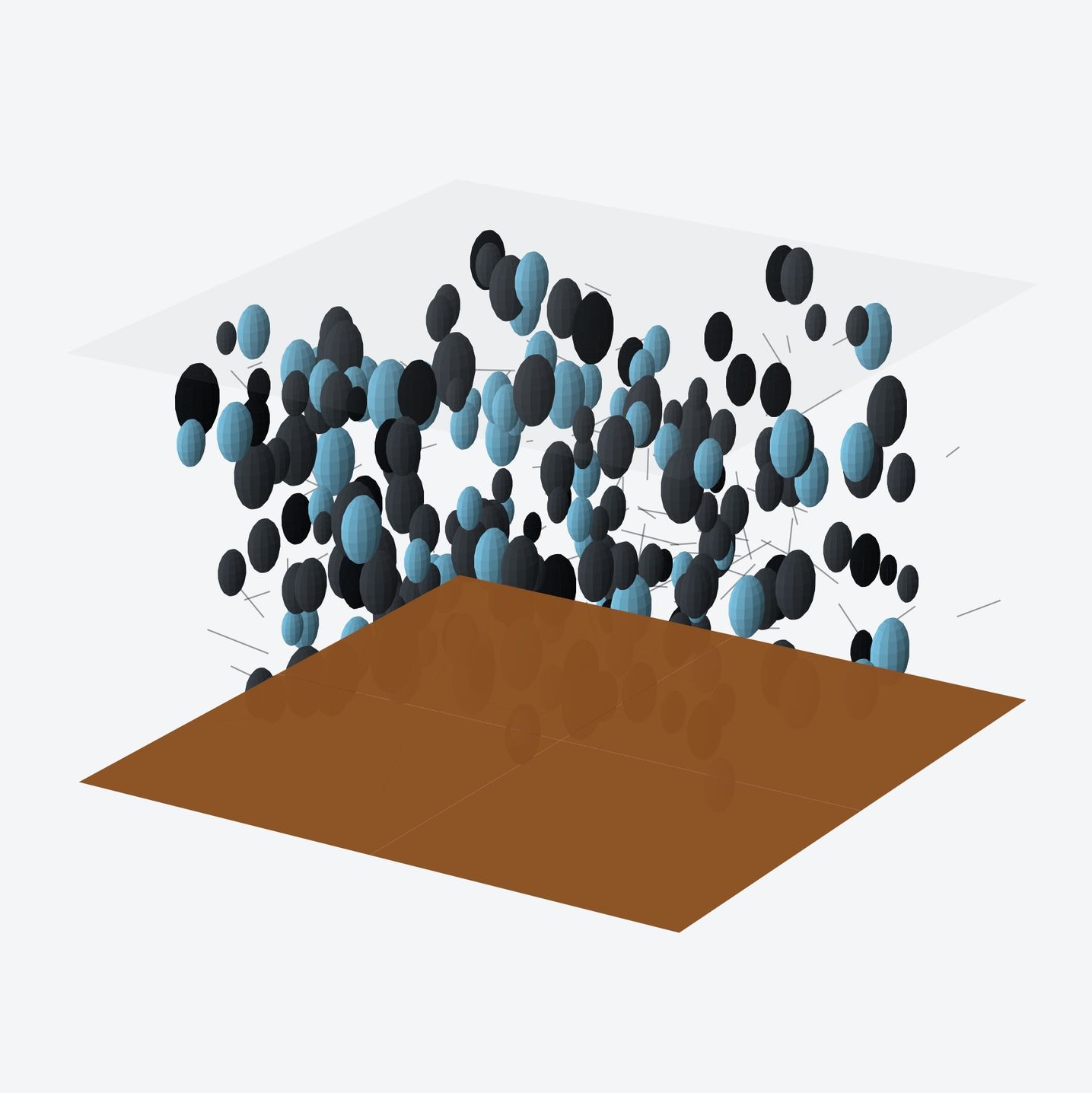 Fig. 5. Cross-sectional concept of a copper-supported porous silicon–carbon anode layer with interconnected conductive domains.
Powder Quality Is Only Half of the Electrode
Silicon-based nanocomposites are unusually sensitive to the surrounding electrode formulation. Binder chemistry influences mechanical integrity and adhesion; the conductive additive affects how current is distributed through expanding particles; the electrolyte and additives determine the chemistry of the solid-electrolyte interphase; and the formation protocol changes the first-cycle interface. A strong raw-material comparison therefore looks at the powder and the test recipe together.
For customers screening multiple candidates, it is useful to keep the electrode recipe fixed while comparing materials, then optimize the formulation after a clear winner emerges. When supplier data use different loadings, binders, electrolytes or voltage windows, the numbers should be treated as context rather than as a direct head-to-head ranking.
When an off-the-shelf powder is close but not quite right, Eata Silicon can review a project-specific specification. Depending on technical feasibility, customization may focus on silicon chemistry, Si/C ratio, carbon source or coating approach, particle-size distribution, secondary-particle morphology, porosity, surface treatment, oxygen level, moisture and selected impurity limits, or a compatible dispersion format.
The most efficient starting point is a target architecture or closest reference material together with the process that follows it. Share the material you are trying to replace or reproduce, the powder characteristics that are already fixed, the electrode or matrix environment and the qualification data that determine whether the material works. We can then evaluate a standard option, a related composite route or a customized specification for your application.
Discuss Your Silicon-Based Nanocomposite Requirement
Send Eata Silicon the target composite family, particle architecture, critical specification points and qualification method. A clear technical brief makes it easier to match the right nano-silicon or silicon-composite route and prepare a focused quotation.
For Research or Industrial Raw Materials, Not For Personal Medical Use!